|
For large magnitude pushes a human or a humanoid
robot must take a step to avoid a fall. Despite some scattered
results, a principled approach towards ``When and where to take a
step" has not yet emerged. Towards this goal, we present the
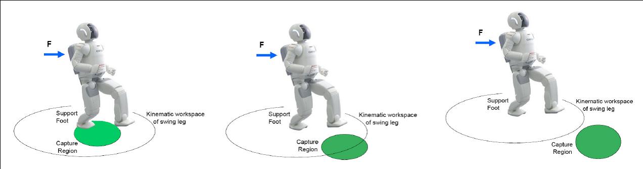
concept of Capture Point, the point on the ground where a humanoid
must step to in order to come to a complete stop. As the push force
progressively grows larger, balance strategies
that are used include moving the Center of Pressure within the foot,
utlizing angular momentum through lunging and
``windmilling'' of appendages, and eventually taking a step.
The location of
the Capture Point relative to the base of support determines which
strategy the robot should adopt to successfully stop in a given
situation.
Computing the Capture Point for a humanoid, in general, is very
difficult or too complex to be practical. However, using the
well-known linear inverted pendulum model, we can compute exact
analytical solutions of the Capture Point. Note that the linear
inverted pendulum model is a significant approximation of the robot
dynamics (more on this below), but the capture point calculation
is exact from this approximate model.
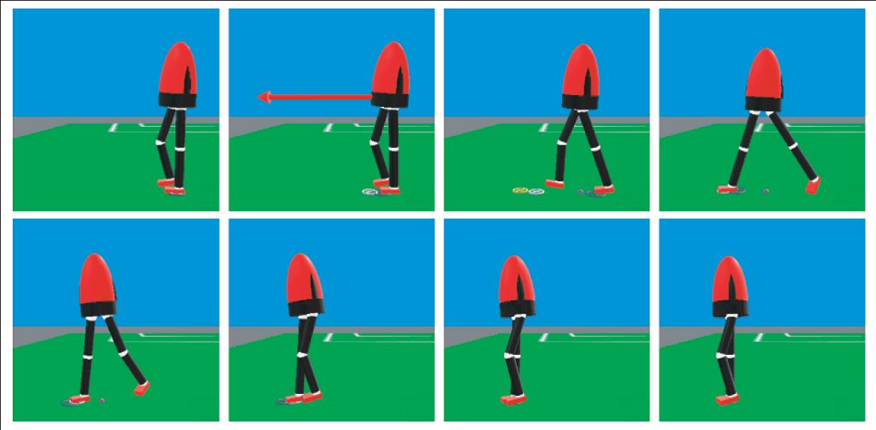 Time elapsed image sequence showing the simulated twelve degree-of-freedom
robot recover from a forward push by taking a step. Snapshots are left to right,
top to bottom, spaced at 0.2second increments. The robot is impulsively pushed,
with a force of 300N for 0.1seconds, corresponding to a velocity change of 1.2ms.
The robot takes a step to a Capture Point to recover balance.
Time elapsed image sequence showing the simulated twelve degree-of-freedom
robot recover from a forward push by taking a step. Snapshots are left to right,
top to bottom, spaced at 0.2second increments. The robot is impulsively pushed,
with a force of 300N for 0.1seconds, corresponding to a velocity change of 1.2ms.
The robot takes a step to a Capture Point to recover balance.
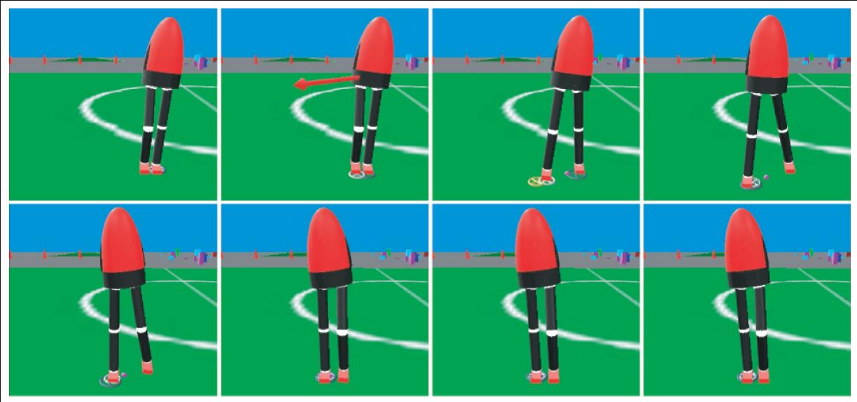 Time elapsed image sequence showing the simulated twelve degree-of-freedom
robot recover from a diagonal push by taking a step. Snapshots are left to right,
top to bottom, spaced at 0.2second increments. The robot is impulsively pushed,
with a force of 200N for 0.1seconds, corresponding to a velocity change of 0.8ms.
The robot takes a step to a Capture Point to recover balance.
Time elapsed image sequence showing the simulated twelve degree-of-freedom
robot recover from a diagonal push by taking a step. Snapshots are left to right,
top to bottom, spaced at 0.2second increments. The robot is impulsively pushed,
with a force of 200N for 0.1seconds, corresponding to a velocity change of 0.8ms.
The robot takes a step to a Capture Point to recover balance.
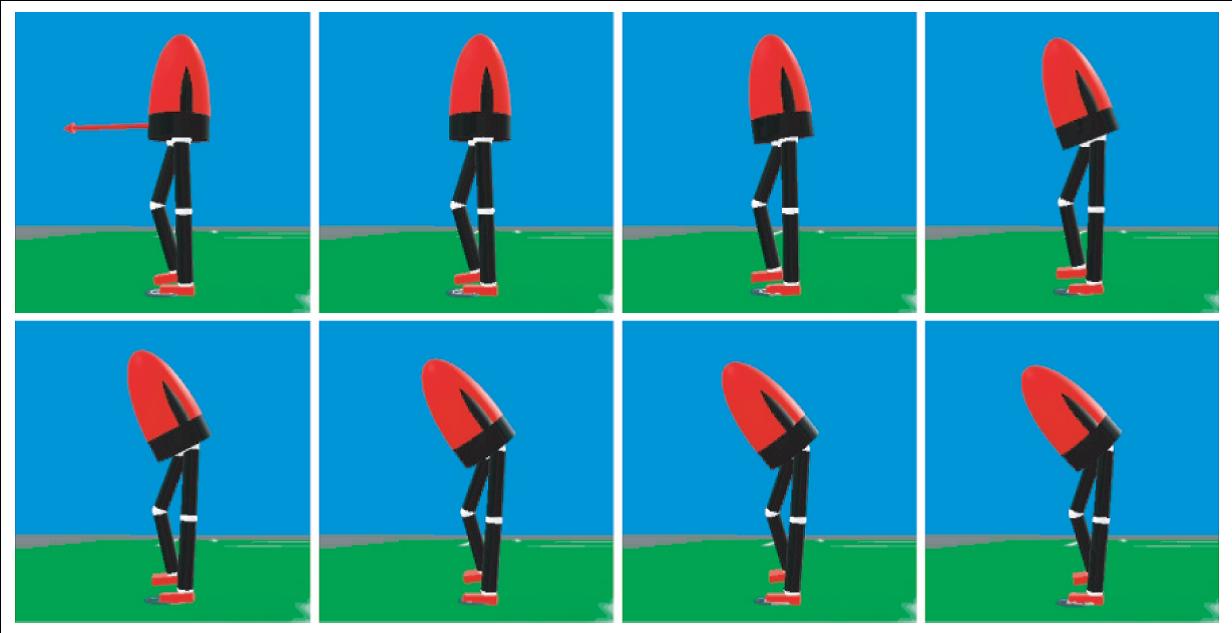 Time elapsed image sequence showing the simulated twelve degree-of-freedom
robot recover from a push by lunging. Snapshots are left to right, top
to bottom, spaced at 0.1second increments. The robot is impulsively
pushed, with a force of 160N for 0.05seconds, corresponding to a velocity
change of 0.32ms. The robot lunges to recover balance, without taking a step.
Time elapsed image sequence showing the simulated twelve degree-of-freedom
robot recover from a push by lunging. Snapshots are left to right, top
to bottom, spaced at 0.1second increments. The robot is impulsively
pushed, with a force of 160N for 0.05seconds, corresponding to a velocity
change of 0.32ms. The robot lunges to recover balance, without taking a step.
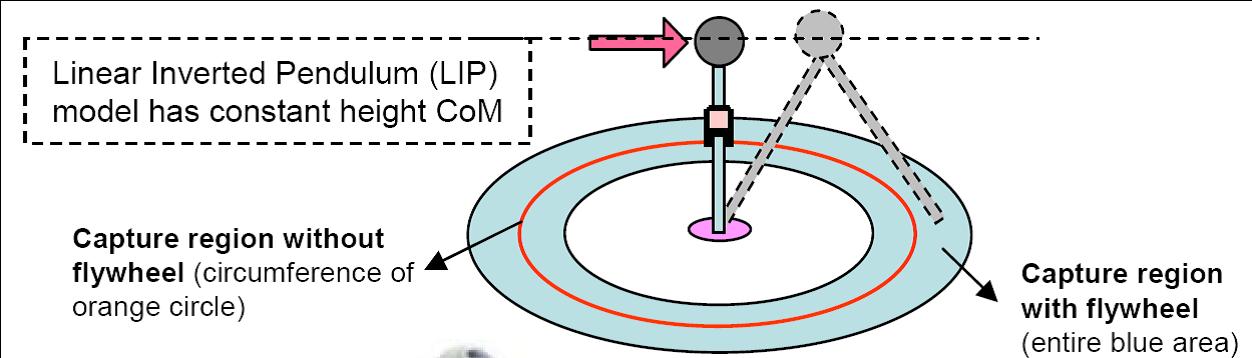
We extend the linear inverted pendulum model to include a flywheel
body and compute exact solutions of the Capture Point for this model. Adding
this rotational inertia enables the humanoid to control its centroidal
angular momentum, much like the way human beings do. We demonstrate
that the Capture Region is significantly enlarged by using the
reserve angular momentum.
Training the robot to improve its performance:
While simple dynamic models are useful for fast computation, model
assumptions and modeling errors lead to stepping in the wrong place
and resulting in large velocity errors after stepping. To address
this we have two major options. One approach is to use
complex models that are more faithful representation of the true
dynamics of the robot. While this is a reasonable approach,
in reality, complex models require significantly more
computing power, sometimes cutting back the advantage gained in
improving the model.
From observation of push recovery behavior of human, we contend
that recovery from a disturbance should not require sophisticated modeling,
accurate physical parameter measurements, or overly constraining limitations on
the walking control system. With this philosophy we adopt a different approach where we
decide to preserve the analytical solution of the simple
linear inverted pendulum model. In order to compensate for
the model deficiency we turn to soft-computing based
learning techniques. Using learning techniques we
update the analytically predicted Capture Points.
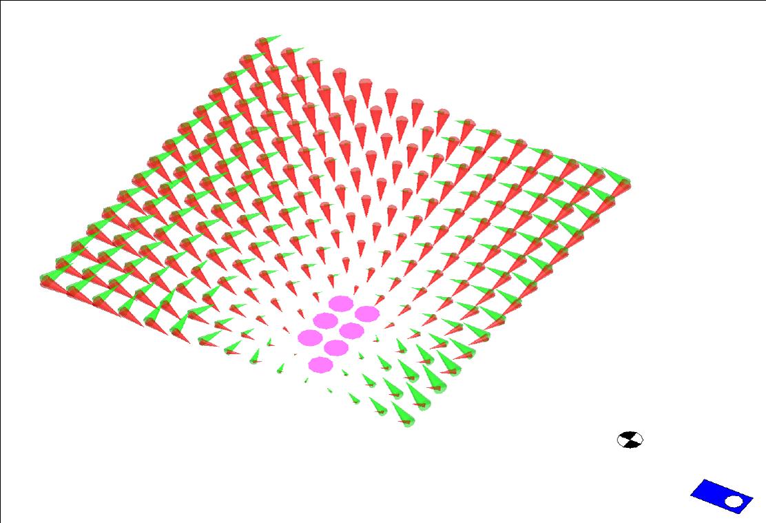 Diagram shows results of stepping to various locations for a given push.
Pink circles show Capture Points. At other points a red arrow shows the resulting vector from
the new support foot to the CoM position and a green arrow shows the resulting
CoM velocity at the point where the CoM comes closest to the center of the support ankle.
The black and white target shows the ground projection of the CoM when the Desired Step
Location Calculator was queried. The blue rectangle shows the location of the current stance
foot. The center of the grid of points is the location of the predicted
Capture Point using the Linear Inverted Pendulum Model.
Diagram shows results of stepping to various locations for a given push.
Pink circles show Capture Points. At other points a red arrow shows the resulting vector from
the new support foot to the CoM position and a green arrow shows the resulting
CoM velocity at the point where the CoM comes closest to the center of the support ankle.
The black and white target shows the ground projection of the CoM when the Desired Step
Location Calculator was queried. The blue rectangle shows the location of the current stance
foot. The center of the grid of points is the location of the predicted
Capture Point using the Linear Inverted Pendulum Model.
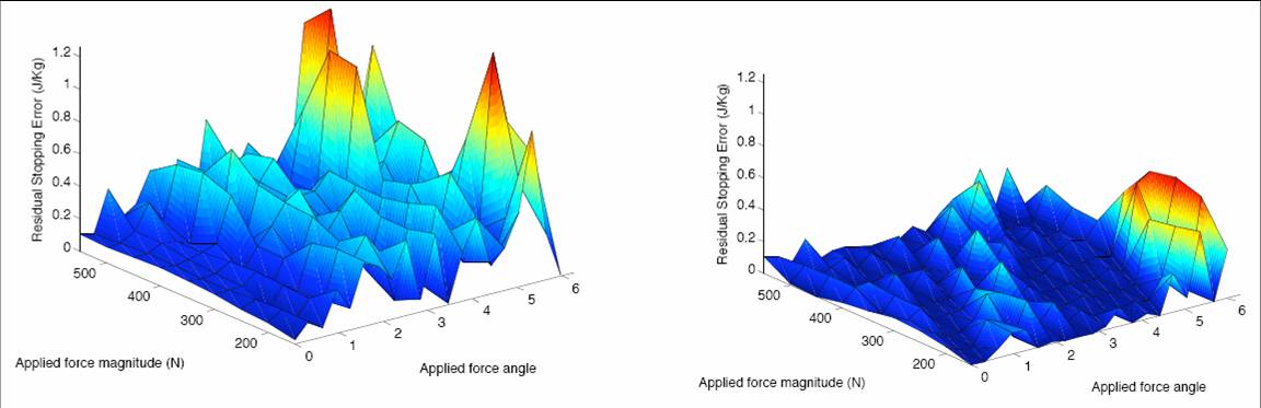 Stopping Error using Capture Points predicted from the Linear Inverted Pendulum Model (left) and
adding a Capture Point offset predicted from the simple curve fit based on the CoM
velocity angle at the decision event(right). Nine different force impulses were
applied from 20 directions. The mean Stopping Error when using the Linear
Inverted Pendulum model is 0.137J/kg, with a stopping success rate of 1 out of 180 trials.
The mean squared error when using the curve fit to predict Capture Point offsets is
0.0192 J/kg, with a success rate of 45 out of 180 trials.
Stopping Error using Capture Points predicted from the Linear Inverted Pendulum Model (left) and
adding a Capture Point offset predicted from the simple curve fit based on the CoM
velocity angle at the decision event(right). Nine different force impulses were
applied from 20 directions. The mean Stopping Error when using the Linear
Inverted Pendulum model is 0.137J/kg, with a stopping success rate of 1 out of 180 trials.
The mean squared error when using the curve fit to predict Capture Point offsets is
0.0192 J/kg, with a success rate of 45 out of 180 trials.
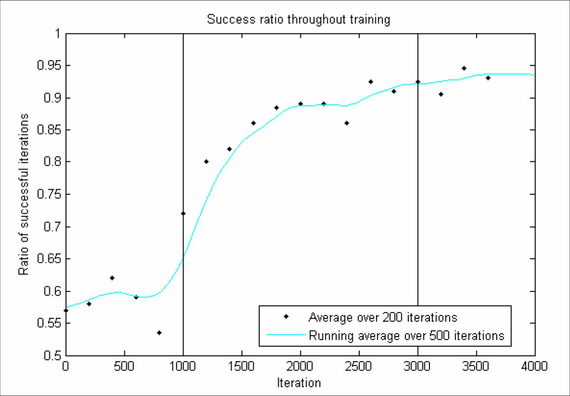 Results of on-line learning. A successful trial has a value of 1, and a failed trial
has a value of 0, regardless of the residual Energy Error. The points plotted represent
the average value over 200 trials. The filtered estimate was found by using a forward/reverse
500 trial running average of the data padded on either side with the average of
the first and last 500 iterations. The vertical lines represent training being turned
on at 1000 iterations and off after 3000 iterations. The disturbance forcs used to test
the controller before and after training are identical.
Results of on-line learning. A successful trial has a value of 1, and a failed trial
has a value of 0, regardless of the residual Energy Error. The points plotted represent
the average value over 200 trials. The filtered estimate was found by using a forward/reverse
500 trial running average of the data padded on either side with the average of
the first and last 500 iterations. The vertical lines represent training being turned
on at 1000 iterations and off after 3000 iterations. The disturbance forcs used to test
the controller before and after training are identical.
 This approach makes a vast improvement to the push recovery
ability of the robot while continuing to be fast. We validate the results
on a three dimensional
humanoid robot simulation with 12 actuated lower body degrees of
freedom, distributed mass, and articulated limbs. Using our learning
approach, robustness to pushes is significantly improved as compared
to using the linear inverted pendulum model without learning.
This approach makes a vast improvement to the push recovery
ability of the robot while continuing to be fast. We validate the results
on a three dimensional
humanoid robot simulation with 12 actuated lower body degrees of
freedom, distributed mass, and articulated limbs. Using our learning
approach, robustness to pushes is significantly improved as compared
to using the linear inverted pendulum model without learning.
|