Recent Papers:
-
J. Chiu and A. Goswami,
Design of A Wearable Scissored-Pair Control Moment Gyroscope (SP-CMG) for Human Balance Assist,
ASME IDETC 2014, Buffalo, New York, August 2014.
(pdf).
Abstract:
Our research examines the feasibility of usign a wearable
scissored-pair control moment gyroscope (CMG) for human balance
assist. The CMG is a momentum exchange device consisting
of a fast spinning flywheel mounted on a gimbal. The gimbal
motion changes the direction of the flywheel rotation axis, which
generates a reactionless torque. A scissored-pair CMG has the
additional advantage of isolating the output torque to a single
axis, where off-axis torques are canceled out. A properly designed
CMG device worn as a backpack can apply a torque in
the sagittal plane of the human trunk. This can help in restoring
postural balance and in fall mitigation.
This paper describes the complete design process of a
scissored-pair CMG device with constraints on size, mass and
dynamic properties for human wearability. A prototype of this
device is built, utilizing a novel dual-flywheel design; it weighs
about 8kg and is able to generate over 20Nm of torque. A custom
hardware is built specifically for verifying the torque output
of the device. To our knowledge this is the only device that generates
the range of reactionless torque given its weight and size.
What is a Control Moment Gyroscope (CMG)?
A basic type of reactionless actuator is an inertia wheel,
where the angular momentum due to a spinning flywheel is exchanged
from the spinning wheel to the body it is attached to.
The inertia wheel and the attached body satisfy the conservation
of angular momentum, thus the momentum exchange, or transfer
of angular momentum, is done by slowing down the flywheel and
accelerating the body. The overall angular momentum of the
combined system (inertia wheel plus body) is constant, however
the angular momentum is transferred between both bodies due
to acceleration and deceleration of the flywheel.
In the
case of an inertia wheel, the direction of the angular momentum
remains in a fixed by the orientation of the flywheel, thus the
torque due to change in angular momentum (by acceleration or
deceleration of the flywheel) are also fixed in the same direction.
A CMG is basically an inertia wheel mounted on an actuated
gimbal. The primary benefit of a CMG
over an inertia wheel is that the output torque is proportional to
both the flywheel angular velocity and the angular velocity of the
gimbal, thus allowing for larger output torques than the torque
required to spin the gimbal (this property is known as “torque
amplification”). This provides a great advantage of being
able to provide large output torques without the necessity of large
actuators.
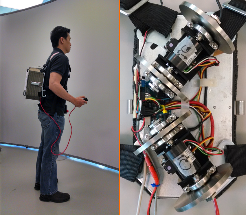
Figure above:
Left: The CMG device is worn as a backpack. Right: The scissored-pair CMG prototype hardware.
-
S.-K. Yun and A. Goswami,
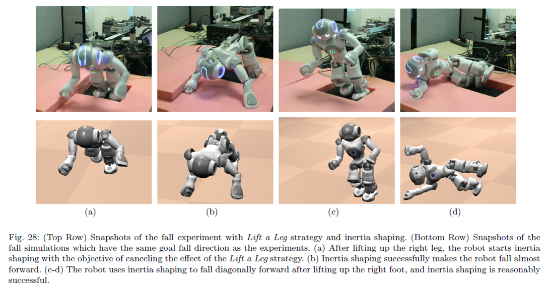
Tripod Fall: Concept and Experiments of a Novel Approach to Humanoid Robot Fall
Damage Reduction,
ICRA 2014, Hongkong, China, May 2014.
(pdf).
Simulation video:
Click Here
Abstract:
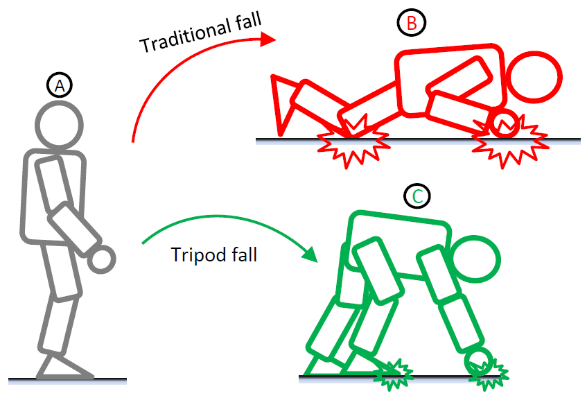
This paper addresses a new control strategy to
reduce the damage to a humanoid robot during a fall. Instead
of following the traditional approach of finding a favorable
configuration with which to fall to the ground, this method
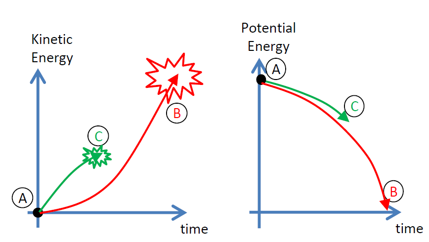
attempts to stop the robot from falling all the way to the ground.
This prevents the full transfer of the robot’s potential energy
to kinetic energy, and consequently results in a milder impact.
The controlled motion of the falling robot involves a sequence of
three deliberate contacts to the ground with the swing foot and
two hands, in that order. In the final configuration the robot’s
center of mass (CoM) remains relatively high from the floor
and the robot has a relatively stable three-point contact with
the ground; hence the name tripod fall. The optimal location of
the three contacts are learned through reinforcement learning
algorithm. The controller is simulated on a full size humanoid,
and experimentally tested on the NAO humanoid robot. In this
work we apply our fall controller only to a forward fall.
Principle of Tripod Fall:
The center of mass (CoM) of a humanoid robot is a uniquely
important point in its dynamics. First of all, it is the effective
location of the robot's total mass, and therefore, the point
where its aggregate linear momentum is naturally defined. It
is also the point through which the resultant gravity force acts.
It should then come as no surprise that virtually all reduced
humanoid models and control algorithms contain the CoM
as an integral component.
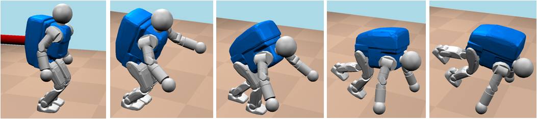
Simulation:
A sequence of steps of a typical tripod fall shown as a set of snapshots from high-fidelity dynamic simulation.
Hardware Experiments:
-
J. Chiu and A. Goswami,
Critical Hitch Angle for Jack-Knife Avoidance During Slow Backing-up
of Vehicle-Trailer System,
Vehicle System Dynamics, Vol. 52, No. 7, 2014.
(pdf).
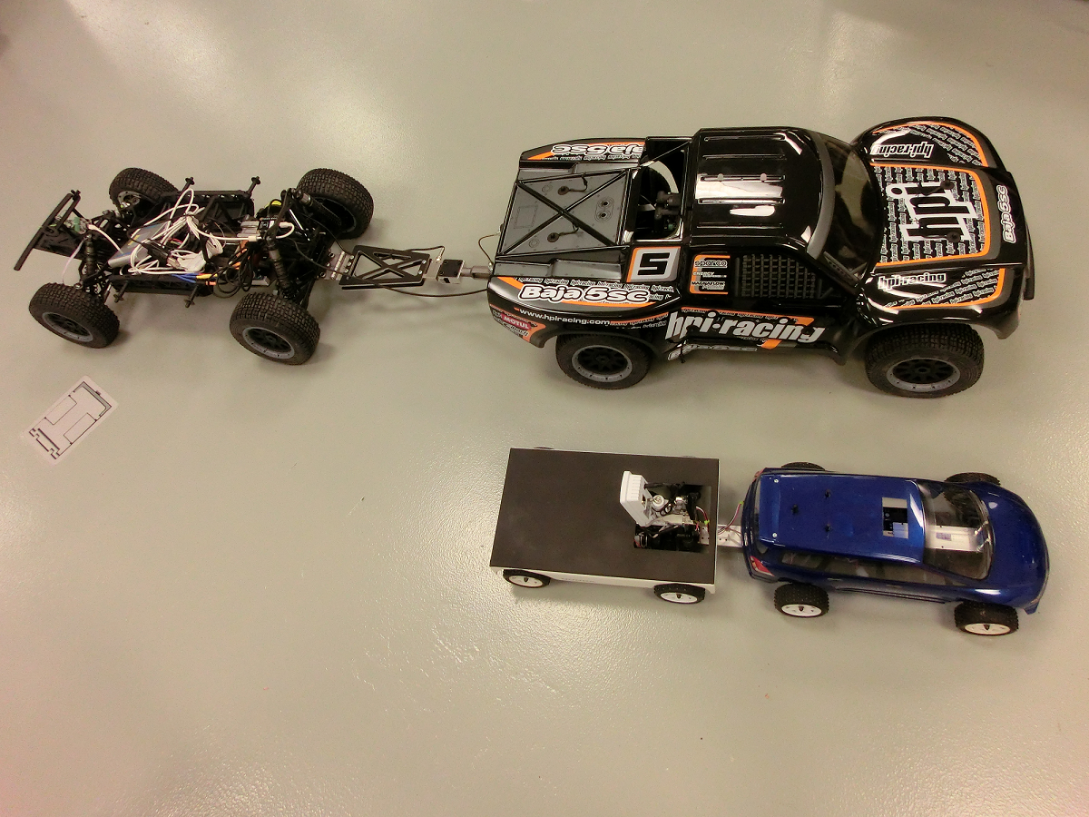
1:5 and 1:10 scale hardware used for this study
Abstract:
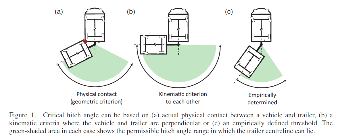
We set out to answer the question: At what hitch angle does it become impossible for a vehicle and
trailer to continue to backing up without getting into a jackknife? Jackknifing during backing up of
trailers occurs when the hitch angle increases to a point such that the vehicle and trailer fold together
about the hitch point like a jackknife. If the backward motion is continued, the jackknife effect progressively
worsens, until the vehicle and trailer are in physical contact with each other. Jackknifing
can result in traffic disruptions and wasted time, and can potentially cause damage or personal injury.
Our goal is to analytically determine the "critical hitch angle", the hitch angle threshold beyond
which a continued reverse motion causes an inescapable jackknifing. In this paper, we provide a formal
definition of critical hitch angle for slow backing up of vehicle-trailer systems on a level solid surface, beyond
which the vehicle must stop backing up and revert to forward motion in order to escape from jackknifing.
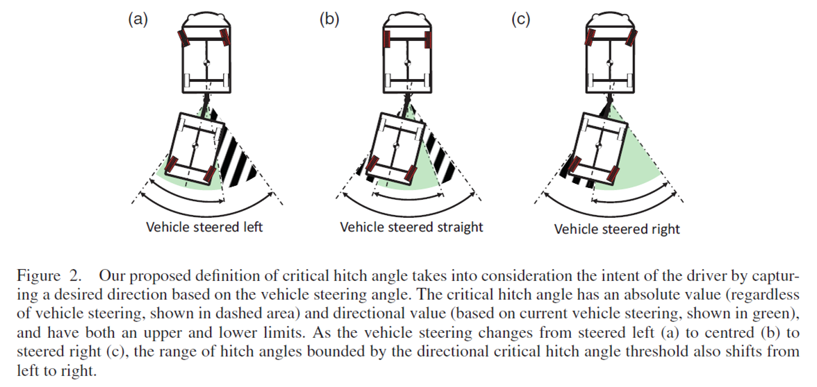
The critical hitch angle is sub-categorised into Absolute and Directional critical
hitch angles depending on the operating constraints and vehicle steering objectives. One solution
for critical hitch angle is posed as a numerical solution to the steady-state conditions of the dynamic equations. The
effects of such hitch angle limitations are demonstrated through simulation. Also, a warning system
making use of the critical hitch angle is proposed. Such warning systems can assist drivers in avoiding jackknifing
while backing up a vehicle-trailer system.
Kinmatic models of single-axis and double-axis trailers:
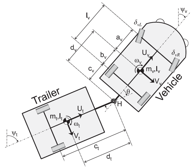
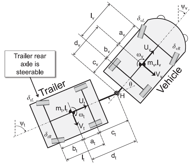
Figure above:
Model parameters for vehicle–trailer systems consisting of a single-axle (left) and a double-axis (right) trailer.
Both vehicles have front-steered wheels. The trailer of the single-axis system is unsteered but the trailer
of the double-axis system has rear-steered wheels. The left and right steering angles of the vehicle are
determined by Ackermann geometry. The vehicle and trailer are connected via
a revolute hitch joint.
Simulation:
A number of ways in which jackknife is defined and characterized.
-
Ambarish Goswami,
Seung-kook Yun,
Umashankar Nagarajan,
Sung-Hee Lee,
KangKang Yin, and
Shivaram Kalyanakrishnan
Direction-changing fall control of humanoid robots: theory and experiments,
Autonomous Robots, Vol. 36, No. 3, March 2014.
(pdf).
Simulation video:
Click Here
Abstract:
Humanoid robots are expected to share human environments in the future and it is
important to ensure the safety of their operation. A serious threat to safety is the
fall of such robots, which can seriously damage the robot itself as well as objects in
its surrounding. Although fall is a rare event in the life of a humanoid robot, the
robot must be equipped with a robust fall strategy since the consequences of fall can be
catastrophic. In this paper we present a strategy to change the default fall direction
of a robot, during the fall. By changing the fall direction the robot may avoid falling
on a delicate object or on a person. Our approach is based on the key observation that
the toppling motion of a robot necessarily occurs at an edge of its support area. To
modify the fall direction the robot needs to change the position and orientation of
this edge vis-a-vis the prohibited directions. We achieve this through intelligent
stepping as soon as the fall is predicted. We compute the optimal stepping location
which results in the safest fall. Additional improvement to the fall controller is
achieved through inertia shaping, which is a principled approach aimed at manipulating
the robot’s cen- troidal inertia, thereby indirectly controlling its fall direction.
We describe the theory behind this approach and demonstrate our results through simulation
and experiments of the Alde- baran NAO H25 robot. To our knowledge, this is the first
implementation of a controller that attempts to change the fall direction of a humanoid robot.
Why humanoids need fall control strategy?
Safety is a primary concern that must be addressed before
humanoid robots can freely exist in interactive human surrounding.
Although the loss of balance and fall are rare in
typical controlled environments, it will be inevitable in physically
interactive environments. Out of a number of possible
situations where safety becomes an issue, one that involves
a fall is particularly worrisome. Fall from an upright posture
can cause damage to the robot itself, to delicate and expensive
objects in the surrounding or can inflict injury to a human
being. Regardless of the substantial progress in humanoid
robot balance control strategies, the possibility of fall remains
real, even unavoidable. Yet, only a few comprehensive studies
of humanoid fall (encompassing fall avoidance, prediction,
and control) have been undertaken in the literature.
A humanoid fall may be caused due to unexpected or
excessive external forces, unusual or unknown slipperiness,
slope or profile of the ground, causing the robot to slip, trip
or topple. In these cases the disturbances that threaten balance
are larger than what the balance controller can handle.
Fall can also result from actuator, power or communication
failure where the balance controller is partially or fully incapacitated.
In this paper we consider only those situations in
which the motor power is retained such that the robot can
execute a prescribed control strategy.
One can ignore the possibility of a fall and wishfully hope
that its effects will not be serious. However, failure studies,
such as in car crash, have taught us against following
this instinct. In fact, planning and simulation of failure situations
can have enormous benefits, including system design
improvements, and support for user safety and confidence.
With this philosophy we closely focus our attention to the
phenomenon of humanoid fall and attempt to develop practical
control strategies to deal with this undesired and traumatic
failure event.
A controller dealing with an accidental fall may have two
primary and distinctly different goals: (a) self-damage minimization
and (b) minimization of damage to others. When
a fall occurs in an open space, a self-damage minimization
strategy can reduce the harmful effects of the ground impact.
If, however, the falling robot can damage nearby objects or
injure persons, the primary objectivewould be to prevent this.
The current paper reports a control strategy for changing the
default fall direction of the robot so that it avoids contact
with surrounding objects or people as a means of minimizing
damage to others. Recently, Wilken et al. (2009) have
reported a third possible goal of a fall controller, that of a
deliberate fall of a humanoid soccer goalie. This is the case
of a strategic fall.
Time is at a premium during the occurrence of a fall; a
single rigid body model of a full-sized humanoid indicates
that a fall from the vertical upright stationary configuration
due to a mild push takes about 800–900 ms (Tan et al. 2006).
In many situations the time to fall can be significantly shorter,
and there is no opportunity for elaborate planning or timeconsuming
control. Yet, through simulation and experiments
we are able to demonstrate that meaningful modification to
the default fall behavior can be achieved in a very short time
and damage to the environment can be avoided.
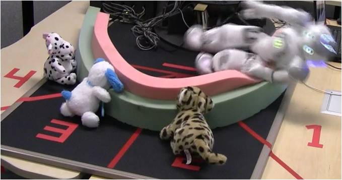
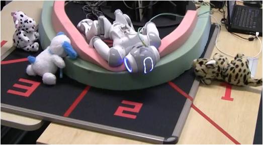
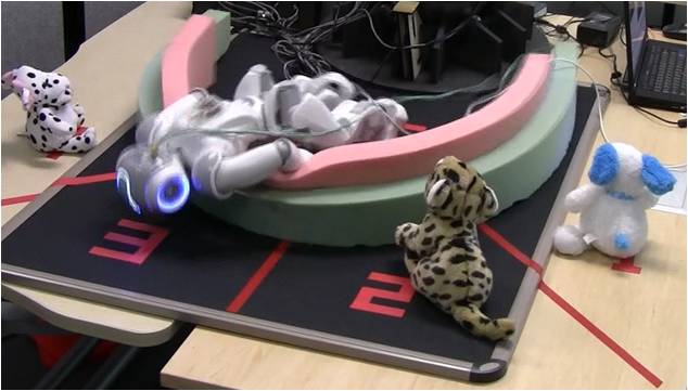
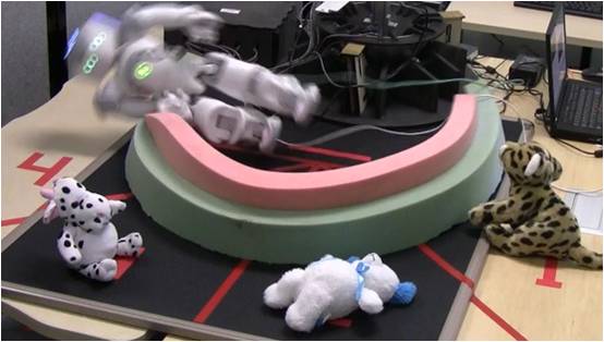
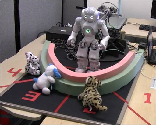
Figure above:
The Aldebaran NAO robot is pushed from behind by a linear
actuator. Its front semicircle is divided into four equal sectors of 45 degree each.
Three dolls are placed in three arbitrary sectors while the fourth sector
is empty. In four trials, we rearrange the dolls in order to change
the location of the empty sector relative to the robot. Under an identical
push the robot successfully changes the fall direction in real time and
falls into the empty sector to avoid hitting the dolls.
-
Federico L. Moro,
Michael Gienger, Ambarish Goswami,
Nikos G. Tsagarakis
and Darwin G. Caldwell
An Attractor-based Whole-Body Motion Control (WBMC) System for Humanoid Robots
Humanoids 2013, Atlanta, GA, October 2013.
(pdf).
Simulation video:
Click Here
Abstract:
This paper presents a novel whole-body torquecontrol
concept for humanoid walking robots. The presented
Whole-Body Motion Control (WBMC) system combines several
unique concepts. First, a computationally efficient gravity
compensation algorithm for floating-base systems is derived.
Second, a novel balancing approach is proposed, which exploits
a set of fundamental physical principles from rigid multi-body
dynamics, such as the overall linear and angular momentum,
and a minimum effort formulation. Third, a set of attractors
is used to implement movement features such as to avoid
joint limits or to create end-effector movements. Superposing
several of these attractors allows to generate complex wholebody
movements to perform different tasks simultaneously. The
modular structure of the proposed control system easily allows
extensions. The presented concepts have been validated both
in simulations, and on the 29-dofs compliant torque-controlled
humanoid robot
COMAN. The WBMC has proven robust to
the unavoidable model errors.
Features:
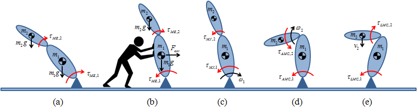
Figure above:
The behavior of the WBMC system is not always easy to predict. The torques generated by the MinEff (minimum effort)
attractor in the case of a 2-link fixed-base
robot, for instance, aim to bring the robot to a vertical position when gravity is the only external force acting on the robot,
as shown in case (a) in the above figure. If another external force
is applied as in case (b), instead, the MinEff locally searches for a configuration that minimizes all external disturbances.
See the paper for other cases, c), d), and e), which are shown above.
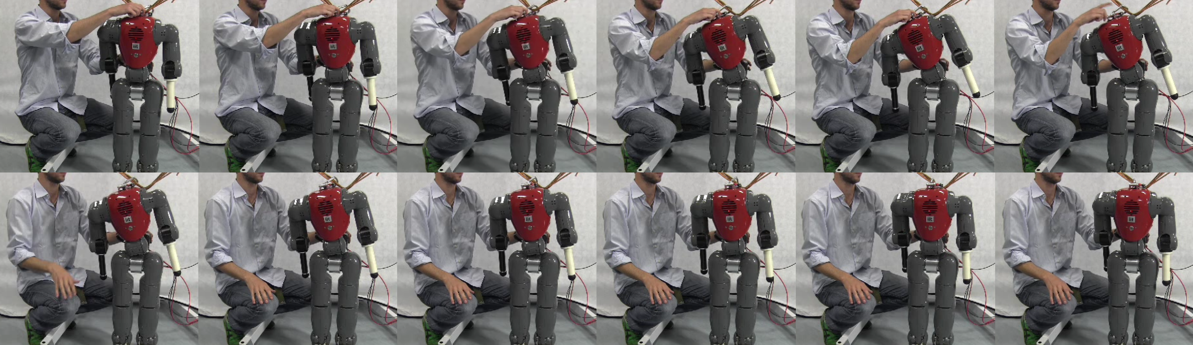
Figure above:
We see snapshots from the video of the experimental validation of the WBMC with the COMAN robot (taken at 2Hz). In this case the robot
configuration is perturbed by forcing the waist roll joint to change its angle. As the robot is released the MinEff (minimum effort)
brings the robot back to a vertical,
minimum effort configuration. The resulting motion is damped by the MomJ (joint moment) attractor, that prevents the velocity to grow uncontrolled.
-
D. Orin, A. Goswami and
S.-H Lee,
Centroidal Dynamics of a Humanoid Robot,
Autonomous Robots, Vol. 35, No. 2, October 2013.
(pdf).
Simulation video:
Click Here
Abstract:
The center of mass (CoM) of a humanoid robot
occupies a special place in its dynamics. As the location of its
effective total mass, and consequently, the point of resultant
action of gravity, the CoM is also the point where the robot's
aggregate linear momentum and angular momentum are naturally
defined. The overarching purpose of this paper is to
refocus our attention to centroidal dynamics: the dynamics
of a humanoid robot projected at its CoM. In this paper we
specifically study the properties, structure and computation
schemes for the centroidal momentum matrix (CMM), which
projects the generalized velocities of a humanoid robot to
its spatial centroidal momentum. Through a transformation
diagram we graphically show the relationship between this
matrix and thewell-known joint-space inertia matrix. We also
introduce the new concept of "average spatial velocity" of the
humanoid that encompasses both linear and angular components
and results in a novel decomposition of the kinetic
energy. Further, we develop a very efficient O(N) algorithm,
expressed in a compact form using spatial notation, for computing
the CMM, centroidal momentum, centroidal inertia,and average spatial velocity.
Finally, as a practical use of centroidal
dynamics we show that a momentum-based balance
controller that directly employs the CMM can significantly
reduce unnecessary trunk bending during balance maintenance
against external disturbance.
Features:
Centroidal Dynamics:
The center of mass (CoM) of a humanoid robot is a uniquely
important point in its dynamics. First of all, it is the effective
location of the robot's total mass, and therefore, the point
where its aggregate linear momentum is naturally defined. It
is also the point through which the resultant gravity force acts.
It should then come as no surprise that virtually all reduced
humanoid models and control algorithms contain the CoM
as an integral component.
In the well-known example of a freely flying multi-link
chain, the average behavior of the chain can be adequately
described in terms of its CoM. While the dynamics of individual
member links can be quite complex, the motion of
the CoM follows a point-mass projectile profile which can be
easily described and communicated. Additionally, the rotational
motion of the aggregate chain obeys the conservation
of angular momentum about the CoM or, the centroidal angular momentum.
For many applications, such reduced description
is instrumental in the analysis and control of the system.
In a similar manner, surprisingly deep insight into the
dynamics of a humanoid robot can be obtained simply by
following the trajectory of its CoM, center of pressure (CoP),
and the lean line connecting these two points. This has been
known for a long time and has been utilized in the study of
human motion. The study of humanoid dynamics has also
inherited this trend and a number of progressively complex
models, some of which are shown above, are currently used
for analysis and control.
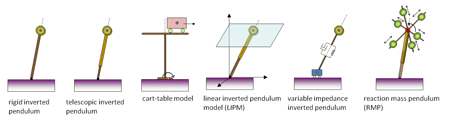
Figure above:
A number of progressively complex "inverted pendulum" models, which are currently used
for the analysis and control of gait and balance of humanoid robots and humans.
Transformation Diagram:
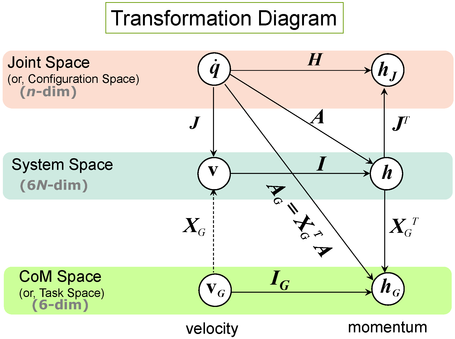
Figure above:
Transformation diagram showing the relations among the velocities
and momenta of a robot. These vector quantities can be expressed
in joint space, system space, or the CoM space of the robot. The matrices
representing the linear transformations between velocities and momenta
in different spaces are also shown in this diagram. The dashed line at the
lower left of the diagram represents a minimum kinetic energy transformation,
which is not a general transformation.
Simulation:
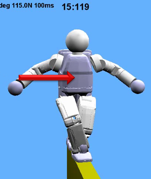
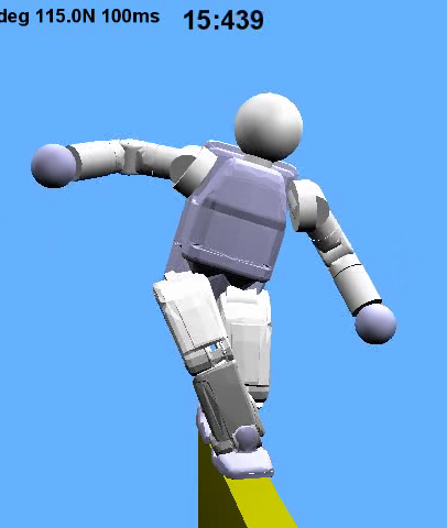
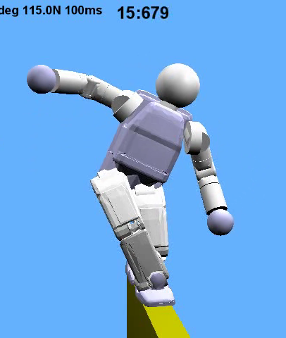
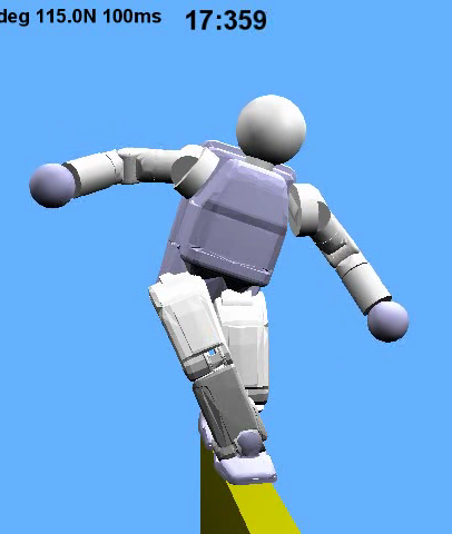
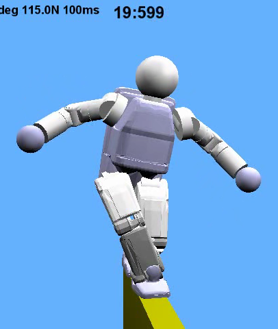

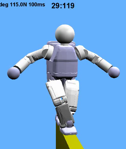
Figure above:
We tested the momentum-based balance controller by simulating
a humanoid robot model. In the simulation
experiment the robot is subjected to a push from the
lateral direction while standing on a narrow support, which is
even slightly narrower than the width the robot's feet. In this
environment, the robot must rotate its upper body in order
to maintain balance, and our controller based on the centroidal momentum matrix
(CMM) creates such a whole body motion in which the whole body
segments including the trunk and arms are engaged to create
the necessary admissible momentum rate change. We see a series of snapshots illustrating when the robot is
subjected to an external push which is applied
at the robot's CoM in the lateral direction from the robot's
right side.
-
S.-H Lee and A. Goswami,
Fall on Backpack: Damage Minimizing Humanoid Fall on Targeted Body Segment Using Momentum Control,
Journal of Computational and Nonlinear Dynamics, Vol. 8, Issue 2, April 2013.
(pdf).
Simulation video:
Click Here
Abstract:
Safety and robustness will become critical issues when humanoid robots start
sharing human environments in the future. In physically interactive human environments,
a catastrophic fall is a major threat to safety and smooth operation of humanoid robots.
It is therefore imperative that humanoid robots be equipped with a comprehensive
fall management strategy.
This paper deals with the problem of reducing the impact damage to a robot
associated with a fall.
A common approach is to employ damage-resistant design and apply impact-absorbing material
to robot limbs, such as the backpack and knee, that are particularly prone to fall
related impacts.
In this paper, we select the backpack to be the most preferred body segment
to experience an impact.
We proceed to propose a control strategy that attempts
to re-orient the robot during the fall such that it impacts the ground with its backpack.
We show that the robot can fall on the backpack even when it starts falling sideways.
This is achieved by generating and redistributing angular momentum among the robot limbs
through dynamic coupling.
The planning and control algorithms for fall are demonstrated in simulation.
Features:
Simulation:

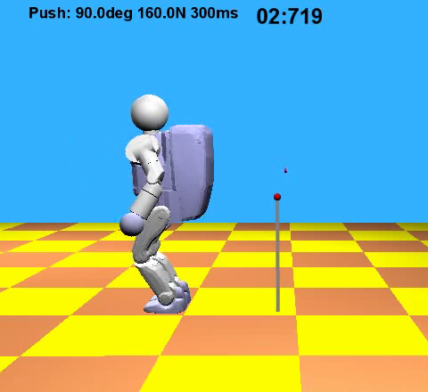
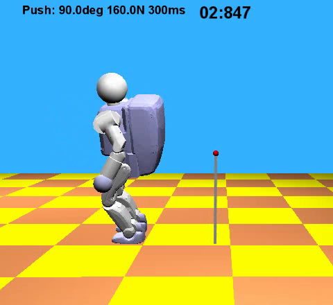
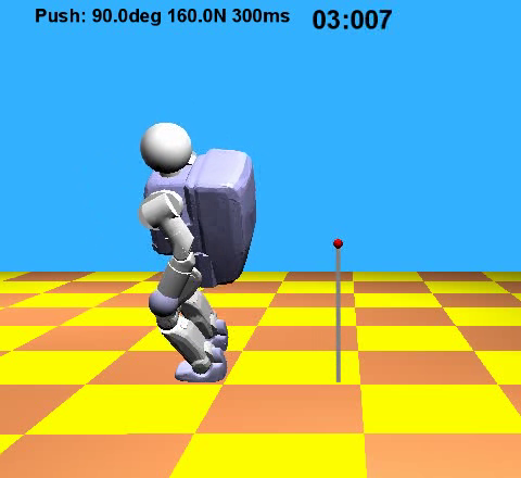
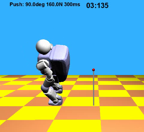
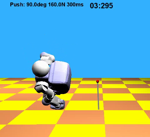
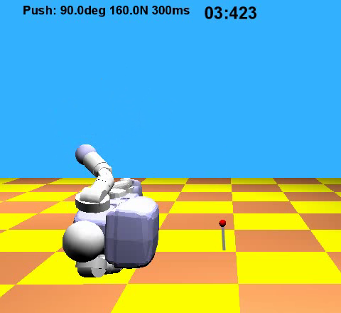
Figure above (no controller):
An external force applied at the CoM of the robot to its left makes the robot fall.
The robot locks all the joints without triggering the fall controller. It falls sideways, and can get
badly damaged.
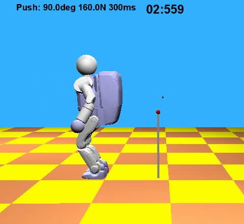

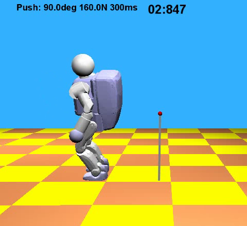
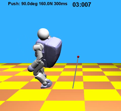
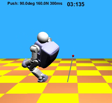
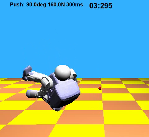
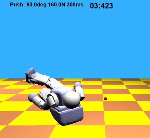
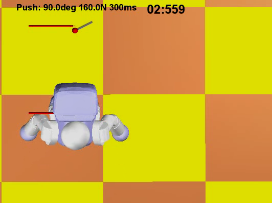
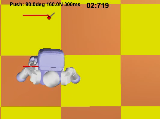
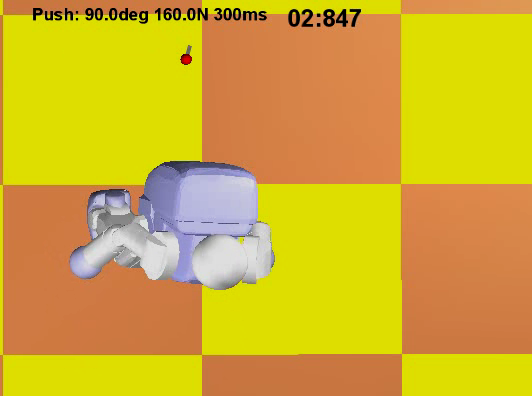
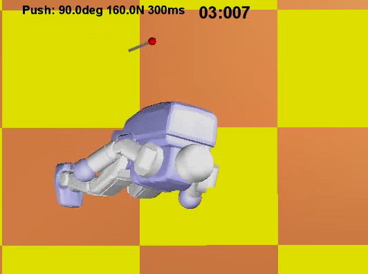
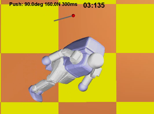
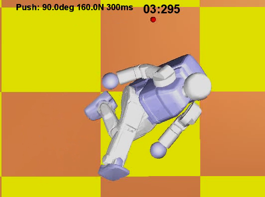
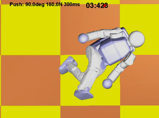
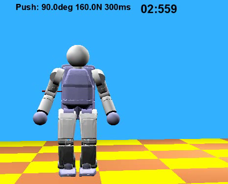
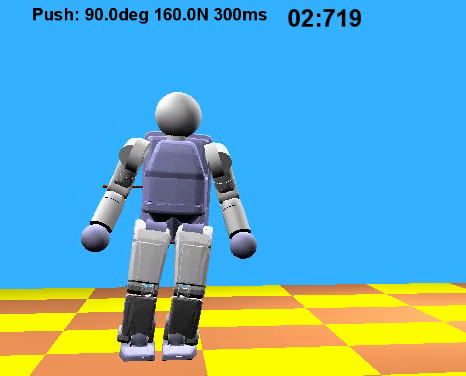
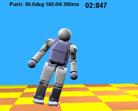
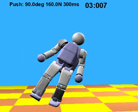
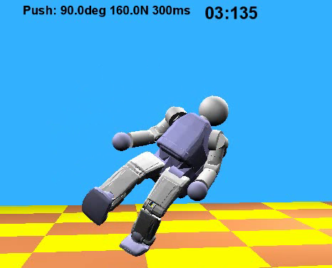
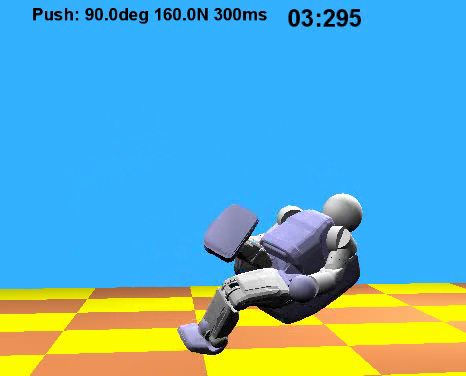
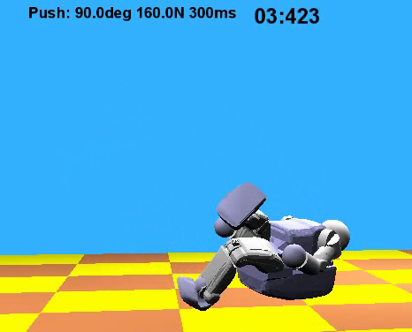
Figure above (with controller):
With our "fall on backpack" fall control strategy, the humanoid can successfully touch the
ground with the backpack under the same push force as above. The assumption is that the design of the
backpack is able to better survive an impact than other
parts of the robot. The top, middle, and bottom
rows show the side, top, and front views, respectively, of the simulation.
-
S.-H Lee and A. Goswami,
A Momentum-based Balance Controller for Humanoid Robots on Non-level and Non-stationary Ground,
Journal of Autonomous Robots, Volume 33, Number 4, November 2012.
(pdf).
Simulation video:
Click Here
Abstract:
Recent research suggests the importance of controlling
rotational dynamics of a humanoid robot in balance maintenance and gait.
In this paper, we present a novel balance strategy
that controls both linear and angular momentum of the robot.
The controller's objective is defined in terms
of the desired momenta, allowing intuitive control
of the balancing behavior of the robot.
By directly determining the ground reaction force (GRF) and the center
of pressure (CoP) at each support foot to realize
the desired momenta, this strategy can deal
with non-level and non-stationary grounds, as well as different
frictional properties at each foot-ground contact.
When the robot cannot realize the desired values of linear and angular momenta simultaneously,
the controller attributes higher priority
to linear momentum at the cost of compromising angular momentum.
This creates a large rotation of the upper body, reminiscent of
the balancing behavior of humans.
We develop a computationally efficient method to
optimize GRFs and CoPs at individual foot by
sequentially solving two small-scale constrained linear least-squares problems.
The balance strategy is demonstrated on a simulated humanoid
robot under experiments such as recovery from unknown external pushes
and balancing on non-level and moving supports.
Features:
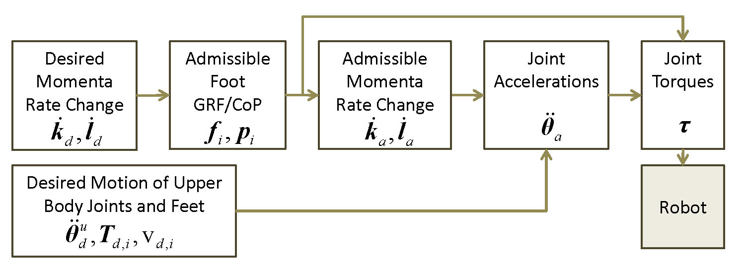
Overview of Momentum-Based Balance Controller.
Simulation:
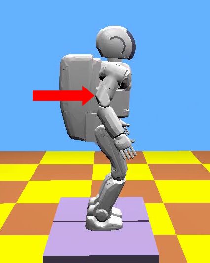
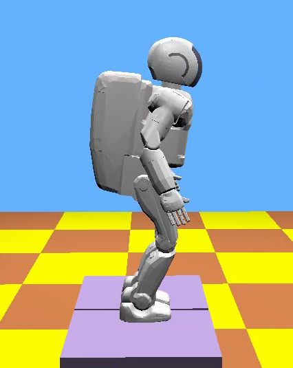
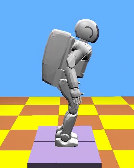
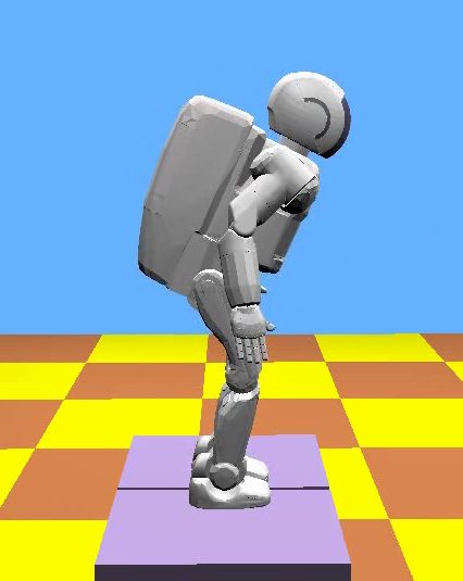
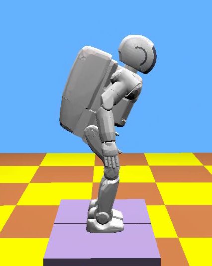
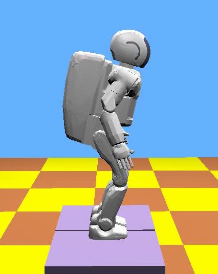

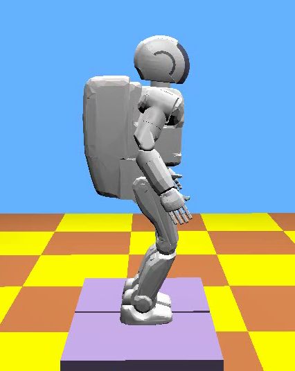
Figure above:
Given a forward push, the balance
controller controls both linear and angular momentum, and generates
a motion comparable to human's balance control behavior.
The robot is standing on stationary level platforms.
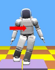
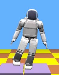
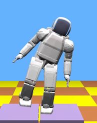
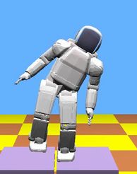
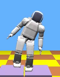
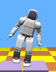
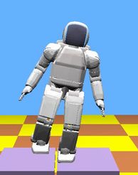
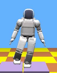
Figure above:
The single-supported robot
on stationary level support successfully recovers from a leftward push.
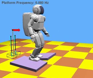
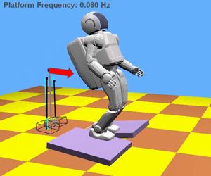
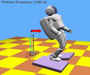
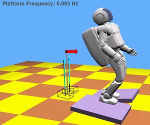
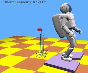
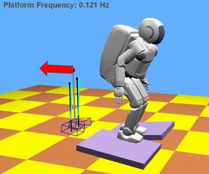
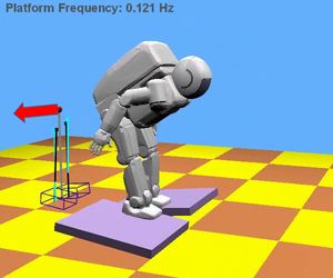
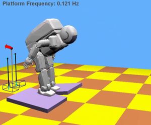
Figure above:
The two supports translate forward and backward with the same speed.
In order to maintain balance, the robot rotates its trunk in a periodic manner.
The red arrows indicate the direction and magnitude of the linear
momentum of the robot. Note that the two feet of the robot have different
ankle angles to conform to the different slopes of the moving platforms.

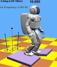
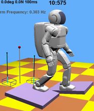
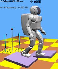
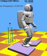
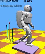
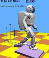
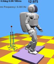
Figure above:
The robot maintains balance on moving supports.
The two foot support surfaces have different inclination angles and out of phase
front-back velocities.
-
J. Chiu and A. Goswami,
Driver Assist for Backing-Up a Vehicle with a Long-Wheelbase Dual-Axle Trailer,
AVEC 2012, Seoul, Korea, September 2012.
(pdf).
Backing up a vehicle and trailer is a tricky task. If you are not careful
you may end up in a jackknife situation in which the trailer and vehicle fold
on each other. We present a human in the loop control where jackknife is avoided using
a trailer with rear steering.
Abstract:
Backing-up of articulated vehicles poses a difficult challenge even
for experienced drivers. While long wheelbase dual-axle trailers provide
a benefit of increased capacity over their single-axle counterparts,
backing-up of such systems is especially difficult. We propose a control
strategy for such systems, introducing concepts of the hitch control space
and no-slip curve derived from no-slip kinematics, allowing backing-up
maneuvers to be intuitive to drivers without experience with trailers. Using
hitch angle feedback, we show these concepts can be used to stabilize the trailer
in back-up motion in the presence of arbitrary driver inputs. The controller is
tested in simulation and on a scale model testbed, demonstrating that robust and
stable backing-up of such systems can be achieved whilst allowing the driver
to maintain full control of the vehicle.
-
T. Koolen, T. de Boer, J. Rebula,
A. Goswami and J. Pratt,
Capturability Based Analysis and Control of Legged Locomotion, Part 1: Application to Three Simple Gait Models,
International Journal of Robotics Research, Vol. 31 No. 9, August 2012.
(pdf).
Abstract:
This paper discusses the analysis and control
of legged locomotion in terms of N-step capturability:
the ability of a legged system to come to a
stop without falling by taking N or fewer steps. We
consider this ability to be crucial to legged locomotion
and a useful, yet not overly restrictive criterion
for stability.
The paper introduces a theoretical framework for assessing
N-step capturability. This framework is used
to analyze three simple models of legged locomotion.
All three models are based on the 3D Linear Inverted
Pendulum Model. The first model relies solely on
a point foot step location to maintain balance, the
second model adds a finite-sized foot, and the third
model enables the use of centroidal angular momentum
by adding a reaction mass. We analyze how
these mechanisms influence N-step capturability, for
any N > 0.
Features:
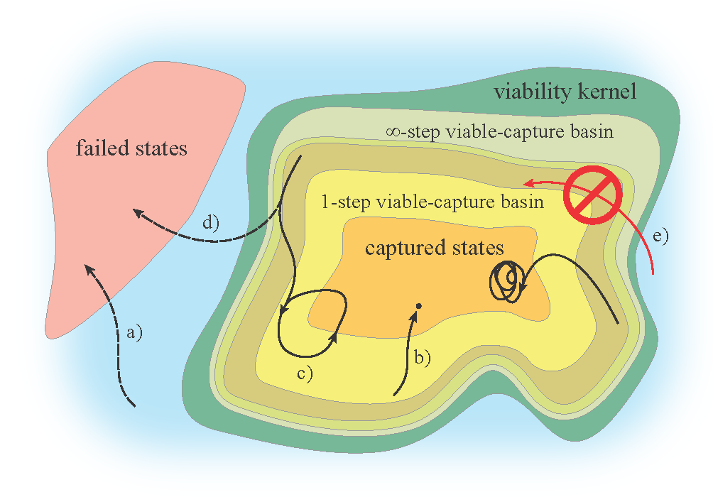
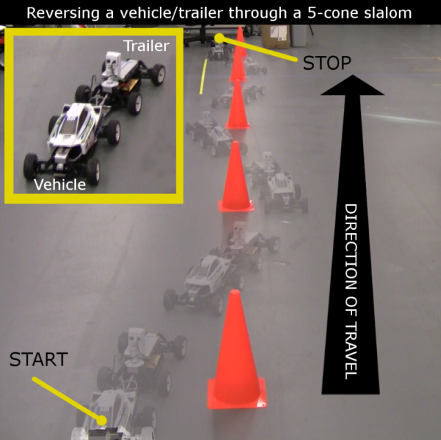
Figure above:
Conceptual view of the state space of a hybrid
dynamic system. Several N-step viable-capture
basins are shown. The boundary between two N-step
viable-capture basins is part of a step surface. The
infinity-step viable-capture basin approximates the viability
kernel. Several evolutions are shown: a) an evolution
starting outside the viability kernel inevitably
ends up in the set of failed states; b) the system starts
in the 1-step viable-capture basin, takes a step, and
comes to a rest at a fixed point inside the set of captured
states (i.e. the 0-step viable-capture basin); c)
an evolution that eventually converges to a limit cycle;
d) an evolution that has the same initial state as
c), but ends up in the set of failed states because the
input u(.) was different; e) impossible evolution: by
definition, it is impossible to enter the viability kernel
if the initial state is outside the viability kernel.
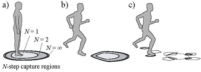
Figure above:
a) A conceptual representation of the N-
step capture regions for a human in a captured state
(standing at rest). b) N-step capture regions for a
running human. The capture regions have decreased
in size and have shifted, as compared to a). c) N-step
capture regions for the same state as b), but with
sparse footholds (e.g. stepping stones in a pond).
The set of failed states has changed, which is re
ected
in the capture regions.
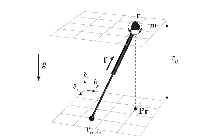
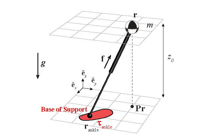
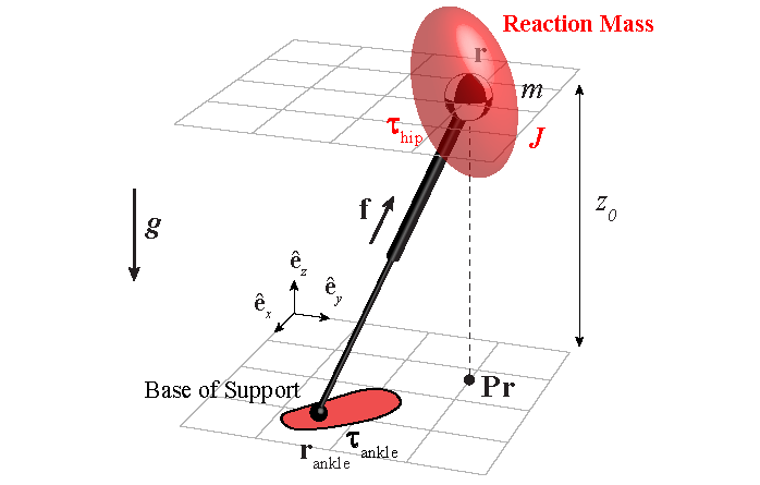
Figure above:
Schematic representations of a 3D-LIPM (Linear Inverted Pendulum Model) with point foot, a 3D-LIPM with finite-sized foot and
a 3D-LIPM with finite-sized
foot and reaction mass with a non-zero mass moment
of inertia tensor.
|